Ups Transformer Wiring Diagram
The thing i am stuck on right now is that for this power range, the windings of most ups transformers available in local market are not properly marked. Uninterrupted power supply 10 uninterruptible power supply circuit diagram.
Transformerless UPS Circuit for Computers (CPU)
None x4x1 h4 h3h2 h1 x2 x3 primary:

Ups transformer wiring diagram. From autocardesign.org estimated reading time 2 mins see details The input voltage of the primary winding of the transformer (tr1) is 240v. The circuit diagram of the ups is shown below, which shows how the batteries in the equipments controls during a power disruption.
Collection of 480 volt to 120 volt transformer wiring diagram. It's quite heavy, i would guess without actually weighing it to be around 15 pounds. Battery backup ups (uninterruptible power supply) systems in the following table can be directly wired to either a 120/240 split phase panel (6k & 10k single phase models) or a 120/208y 3 phase panel (10k, 15k, 20k, 30k, & 40k 3 phase models).
Batteries wiring connections and diagrams. Physically there are five winding taps on output. Ctrlf enter the name of the firm or digital value of the model samsung microwave ovens schematic diagrams and service manuals.
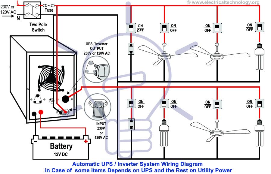
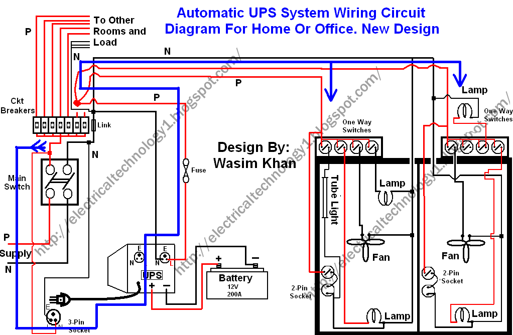
Primary winding lower thick wire 230v secondary winding upper thin wire 2kv. Since neutral and earth are bonded in the consumer unit the system sees this as a short circuit and so a large current will flow which will blow the fuse or trip a circuit breaker. Automatic ups system wiring diagram in case of some items depends on ups and rest depends on main power at office or home.
Now, according to the below ups connection diagram, connect an extra wire (phase) to those appliances where we have already connected phase and neutral wires from (power house & db) (i.e., two wire as phase (live) as shown in the below fig). A transformer is a piece of static electrical equipment. Hps imperator tm industrial control transformer wiring diagrams issue date:
To help our customers understand proper connections for dual primary and/or dual secondary transfomers we have prepared 4 examples (below) on a hypothetical dual primary & dual secondary transformer. It is extremely easy to draw a wiring diagram; October 2007 rev4 page 1 of 9
The reverse of this is known as a step down transformer. A wiring diagram is a streamlined traditional photographic depiction of an electric circuit. October 18, 2019 1 margaret byrd.
3 and is important to understand for the remainder of this paper. Generalgeneral electrical connection diagramsacme® transformer™ wiring diagrams primary: The three power phases are applied to the transformer windings (green lines) that are
Nt_8858 microwave oven wiring diagram on whirlpool microwave motor diagram schematic wiring. Transformer isolation the actual wiring diagram of a transformer, is shown in fig. The secondary winding of the transformer (tr2) can be raised up to 15v if the value is at least 12v.
As you're looking at the transformer, you can see on the left the 6, 5, 2, 1 and you can see how those are two separate pieces and if you connect 5 and 2 together, then it's basically, from top to bottom, one series circuit. Hey @joefo.installing your ring video doorbell 3 to a transformer should be pretty simple. The smaller leads are about 16 gauge and the other two leads coming out of the other side are about 12 gauge.
Basic transformer hook up data. The key to proper connections is the phasing information. Wiring diagrams for hardwire ups.
The 6k & 10k single phase models have built in isolation transformers that create their own neutral. Provide continuous supply in case of supply outage protection against voltage spikes frequency fluctuation and against distortion in voltage wave form. Possible transformer locations in the “single mains” ups configuration.
None x4x1 h4 h3 h2 h1 x2x3 primary: Home > transformer index > power > basic hook up data. The laminated core of the transformer measures 4 1/2 across the top, 2 1/2 wide and 3 3/4 high.
/ 12, 2 /2% anfc, 4, 2 1/2% bnfc x4 x1 h10 h2 h3 h1 x2. In the diagram above, taking an installation without an isolation transformer, the device has an earth fault (for example a live conductor has shorted to the chassis). It stands for the physical parts of the electric circuit as geometric forms, with the actual power and connection connections in between them as slim edges.
Pin on electric golf cart equivalent circuit of a transformer is a schematic representation of a practical transformer that shows all electrical parameters such as winding resistance reactance admittance susceptance primary and secondary voltages currents etc. The circuit drawn pertains to a regular industrial ups (uninterruptible power supply), which shows how the batteries take control during an outage in electrical supply or variation beyond the normal limits of the voltage line, without disruption on the operation. The transformer consists of three windings.
Manual ups wiring diagram with change over switch system. Read single pole dimmer switch wiring diagram download. Where we don’t have a wiring diagram for your device, you can find steps outlined here in this help center article here.if you’re uncomfortable with wiring your device, we encourage our neighbors to contact a licensed electrician.
And no need to connect extra neutral wire from ups as it is already installed & connected before. If you have any questions regarding these wiring diagrams or are having any difficulty correctly installing our transformers, please contact hps customer service or technical support in the u.s. You just need to have a good.
Automatic ups system wiring circuit diagram for home or office (new design with one live wire) wiring and installation. Solved ups transformer windings technical 12v from standard single phase transformers ei electronic power how to connect a homemade inverter circuit 12 0 centre tapped specifications free vs 4 simple uninterruptible supply. Solar panel wiring & installation diagrams.
Posted wednesday, january 11, 2012.
Automatic and manual UPS system wiring for home or office with circuit diagram

Wiring A Battery Backup Power UPS To A Subpanel Battery Backup Power, Inc.

Desi UPS Circuit Diagram With Transformer Formula Electrical Tutorials in Hindi/Urdu

Automatic and manual UPS system wiring for home or office with circuit diagram

Automatic UPS system wiring Electrical & Electronic Technology

Automatic UPS Wiring for Partial Load The rest Depends on Main Power
Proposed circuit diagram of lineinteractive transformerless UPS system. Download Scientific
Uninterruptible Power Supply (UPS) Basic Circuit Diagram EEWeb Community

Online Ups Wiring Diagram Wiring Diagram

UPS uninterruptible power supply circuit diagram

Released Step Up Transformer Wiring Diagrams Read Online 486 Released Read Online
> circuits > Automatic UPS system wiring circuit diagram New Design Very simple for Home or
UPS uninterruptible power supply circuit diagram
Guidelines for using isolation transformers in data center UPS systems
UPS design transformerfree vs transformerbased EE Publishers

Automatic and manual UPS system wiring for home or office with circuit diagram

Automatic and manual UPS system wiring for home or office with circuit diagram

Diagram For Wiring Two Light Switches From One Power Supply
Wiring Diagrams For Hardwire UPS Battery Backup Power, Inc.
