Contactor Wiring Diagram With Timer Pdf
Contactor wiring diagram start stop; It reveals the elements of the circuit as simplified forms and also the power and signal links between the gadgets.
12+ Schneider Electric Single Phase Contactor Wiring

They can be used as a guide when wiring the controller.

Contactor wiring diagram with timer pdf. Contactor breakers limit switch no static control standard elementary diagram symbols. Emc 89336eec lvd 7323eec wd081 contactor wiring diagram with timer on delay timer circuit diagram wiring diagram contactor with push button circuit diagram of delay timer on off power off delay timer circuit diagram 2 way lighting circuit triggering transformer push button fan switch light. Fevereiro 7, 2022 post category:
Basics 13 valve limit switch legend : 3 pole contactor without base contact 4 pole contactor with 4 n.o. Basics 8 aov elementary & block diagram :
When c3 is energized, its auxiliary open links will be closed and vice versa (i.e. You’ll be able to often rely on wiring diagram as an crucial reference that may assist you to save money and time. If you wire this side to the battery the contactor will not work.
Otherwise the arrangement wont function as it. Eastern illinois beach volleyball post comments: Basics 10 480 v pump schematic.
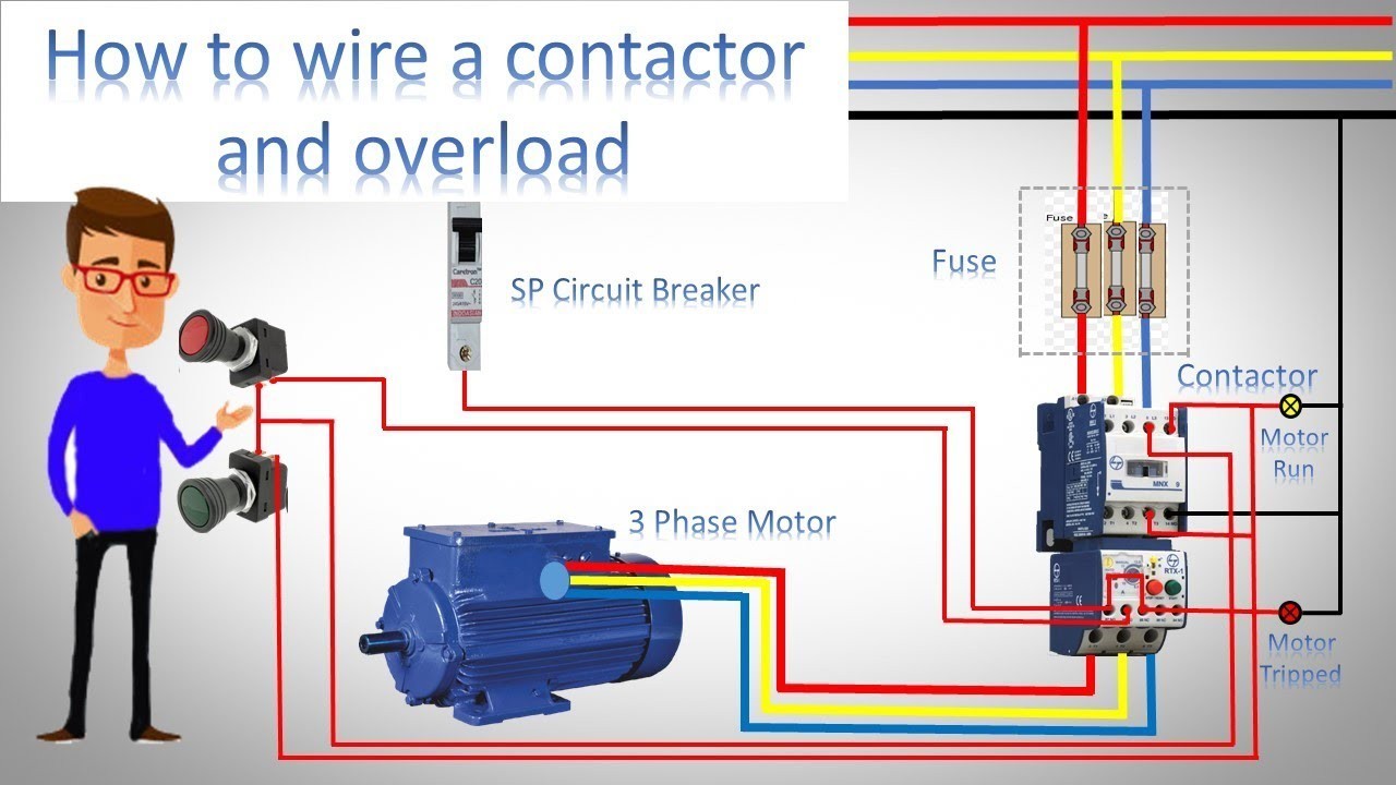
Hager ezn002 delay off timer. Note that one one of the contactor acts as a switch for the start button. 3 phase contactor wiring diagram pdf electrical wiring diagram electrical wiring electrical circuit diagram.
Contactor these diagrams are current at the time of publication check the wiring diagram supplied with the motor. Madcomics timer switch wiring diagram hager surface mount 24hr analog eh 010 instruction manual pdf to connect 225 eh711 24hrs time contactor digital eg103b e welcome electronic lighting i need it is wall. It requires a small amount of control circuit to turn on and off the load.
Remove/flip back the top of the control box. This contactor draws just under 1a at 14v. Pdf contactor wiring diagram with timer.
Put the delay timer mount on the stud from the last step, with the bend in the metal facing as shown below. Typical wiring diagrams for push button control stations 5 explanation of symbols momentary contact push button auxiliary contactsoperate when operating coil of contactor depressing button opens and parent switch. These are the wiring diagrams for lighting and heating contactors.
The diagram symbols in table 1 are used by square d and where applicable conform to nema national electrical manufacturers a ssociation. Legrand 03700 timer wiring timer wire electrition. Schneider electric low voltage distribution cct15232 mins timer 05 20min.
When the supply provided to timer the light bulb will be off. When voltage is applied to the input terminals the contactor is latched into position (coil is removed from the circuit while control A simple circuit diagram either of the two start buttons will close the contactor , either of the stop buttons will open the contactor.
Basics 10 480 v pump schematic : Note that one one of the contactor acts as a switch for the start button. See image below for an example of 3 wire control being used to pull in a contactor to start a 3 phase motor.
The trouble really is that all car is different. The following diagram is shown for a 3 wire control of a delta star connection. Auxiliary contacts each contactor may use one single or one double auxiliary contact block on each side of the base.
Pdf contactor wiring diagram with timer. Contactor while a second pulse on an alternate leg returns the contactor to its original state. Remove the terminal block nut, terminal block, and insulator.
First we understand what is no and nc point. Basics 9 4.16 kv pump schematic : When this post is grounded the contactor is closed.
800 x 600 px, source: Next frustrating to remove, replace or fix the wiring in an automobile, having an accurate and detailed contactor wiring diagram pdf is vital to the. Pdf contactor wiring diagram with timer.
3 phase motor starter wiring diagram pdf. Pdf contactor wiring diagram with timer. Hager timer switch wiring diagram.
The complete guide of single phase motor wiring with circuit breaker and contactor diagram electrical circuit diagram circuit diagram electrical wiring diagram. Basics 14 aov schematic (with block included) basics 15 wiring (or connection.
3 Phase Contactor Wiring Diagram Start Stop Pdf 2 pole

How to wire Schneider LC1D contactor

Timer And Contactor R Relay Diagram / Contactor vs Motor
Contactor Wiring Diagram Pdf

Schneider Contactor Wiring Diagram Pdf Electrical Wiring
Diagram Installation 3 Phase Contactor Wiring Diagram
Wiring Diagram For Timer And Contactor

3 Phase Contactor Wiring Diagram Start Stop Pdf

Get Contactor Wiring Diagram Pdf Pictures

Impulse Timer Lighting Contactor / Lighting Contactor
Wiring Diagram For Timer And Contactor
3 Phase Contactor With Overload Wiring Diagram Pdf

Contactor Wiring Diagram With Timer Pdf

54 Timer Connection With Contactor Wiring Diagram Plan
3 Phase Contactor With Overload Wiring Diagram Pdf

Timer And Contactor R Relay Diagram Control 240 Volt
[FY_4887] Wiring Diagram For Contactors Wiring Diagram

35 Unique Contactor Relay Wiring Diagram
Timer And Contactor R Relay Diagram wiring a contactor